

Would like be able to port the schematic to an on-line PCB supplier or to a Gerber file. I guess you'll have to be mindful of the line width and spacing used for a particular font when sizes go below 4.As … Re: Recommended Low cost High quality schematic capture & PCB layout. If you have money to burn you could send out a font test board to see what works and what doesn't. Ask them if you don't see it listed on their website. Local settings override global settings.ģ) Good question. In the Component Properties dialog window select the tab, enable the Custom Font Size: and Component Marking Font for Text Object options, select the desired font size using the drop-list and click on the button.įor a global change: View > Component Markings. Rotation is also possible while dragging the text by pressing the bar or the " r" hotkey.Ģ) For a local change right-click on the component (not its pads) and select " Properties." in the pop-up menu to bring up the Component Properties dialog window. Using the mouse, left-drag the text to the desired location. Tutorial is very important document for people new to DipTrace! Hope my suggestions will appear in this Forum.ġ) Press softkey to activate " Move component texts" (you should see the Hint area indicate the mode change). I was very impressed with the Video on your site and expected similar clarity in Tutorial. In my opinion, the Tutorial needs a review of both, Semantic and Writing Style. I realize a lot of effort to write this Tutorial. The same objects are repeated with different names. It is like a "river" of words without end. Very difficult to return back to the same place in Tutorial switching attention between Tutorial and actual PCB. One of the main issue _there is no accent by Font and/or Style for descriptions of major steps (what Icon to use for described feature, etc.).

My inner is trying to find any reason not to go back to Tutorial. So far, I got through 45 pages and found very difficult to follow instructions.
Diptrace pcb layout tutorial full#
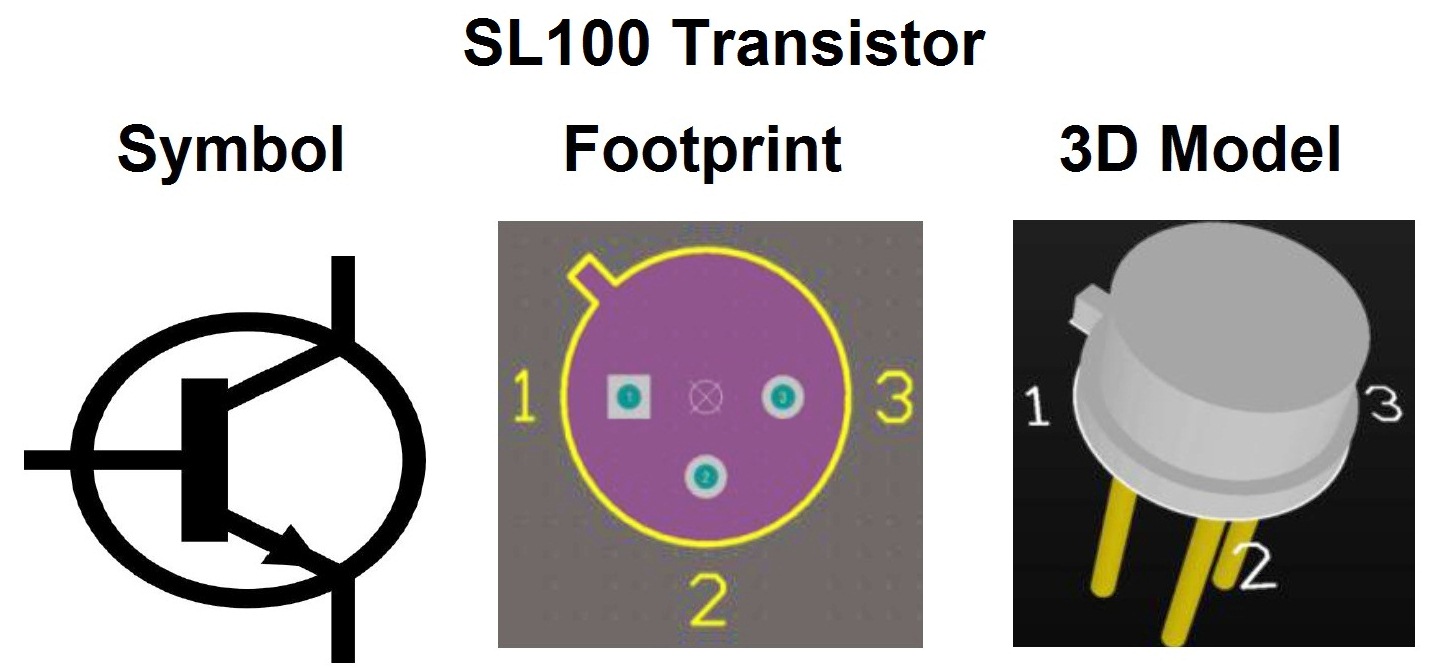
I'm trying to learn a free-copy of DipTrace before buying full software package. Statistics: Posted by lorley - Today, 00:11 The thing is that all the ICs are on the bottom layer, which are completely wrong from mirrored routing, and everything on the top layer is basic connectors which I think can be mirrored without it actually creating any fault, the only thing on top layer im not sure about are potentiometers, maybe they would have reversed response? or maybe not and this top layer could be mirrored without electrical or mechanical changes at all, only different positioning?Įither way If there was some way to make the top layer into the bottom layer and vice versa this would greatly help this situation and make the PCB easily fixable.įor a second I thought this was possible in layer properties>layer stack up but unfortunately it doesnt seem to have any effect when I swap the layers places with this option The bottom layer as viewed through Diptrace is a mirrored ''x ray'' view, but I built on this layer as if it was viewed normally. In my recent PCBs I started to use schematics as it makes things a million times easier and this made me realise a fatal flaw with the first PCB I built without any schematic. In one of the first PCBs I designed as part of a larger project I didnt use a schematic, simply built it by eye. Statistics: Posted by carlmart - Today, 08:48 But it seems few or no people is coming around. Let's hope there's someone around that is finding therapeutic to be active on forums like this. Now I'm back on the saddle with some simpler projects, mostly discrete, nothing digital, little or no SMD parts.ĭue to the present situation, it's quite likely I will have to build the prototypes myself, so I will quite likely work on a single side of the pcb, with as few as possible wires on the component side, for those situations that can be avoided.Īs some of the designs are old and from a time where the industry also built things single sided, thing shouldn't be particularly difficult.ġ) How do you split a trace at a specific point? I didn't find an option like "break trace" as I had used on other pcb programs.Ģ) How do I convert a part I designed, based on an library part transistor, into an active part that I can add to my personal parts library?ģ) Is there a way to know which transistors have which pin assignment, even if they name is different, so I can use on my design? How? Going one by one?
Diptrace pcb layout tutorial pro#
I do know that I went through the tutorial from beginning to end, designed many components not on the library and mastered all things to make a pro design. It's been close to five years since I designed my last pcb with DipTrace, and my 72 years old age does not make it better to remind how I did things back then


 0 kommentar(er)
